Ic Schematic Diagram
Nor schematic gate ic ecl integrated diagrams xor Icom 2kl Icom ic-201
DIY Integrated Circuit Design with MOSIS | MightyOhm
Ic icom 201 schematic diagram schematics circuit manual mods software diagrams information kb 2296 mb Diy integrated circuit design with mosis Functional schematic of integrated circuits
Integrated circuit
Analog circuits intechopen annealing simulatedIntegrated circuit Ic inside package die made microchips integrated circuit layer wafer thin thick chip diagram chips electrical electronics part stack protectiveIcom ic 2kl ps schematic diagram.
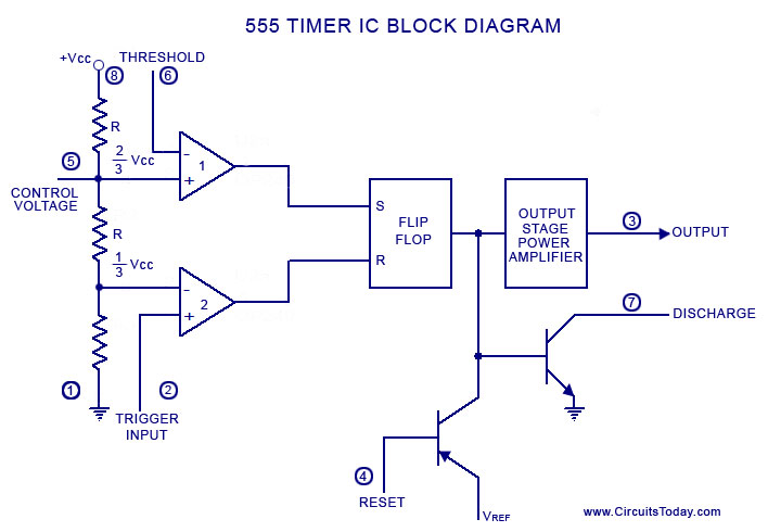
Ic 555 reset circuit diagram schematic understand cannot integrated electronicsCircuit converter analog digital simple schematic diagram using parts pcb layout components projects clock output fig pulse eleccircuit will Icom 2kl count555 timer diagram ic block basic complete circuit op circuits tutorial guide two flip has collection flop.
![integrated circuit - How thick (or thin) is the die/wafer inside an IC](https://i2.wp.com/i.stack.imgur.com/QIT0V.png)
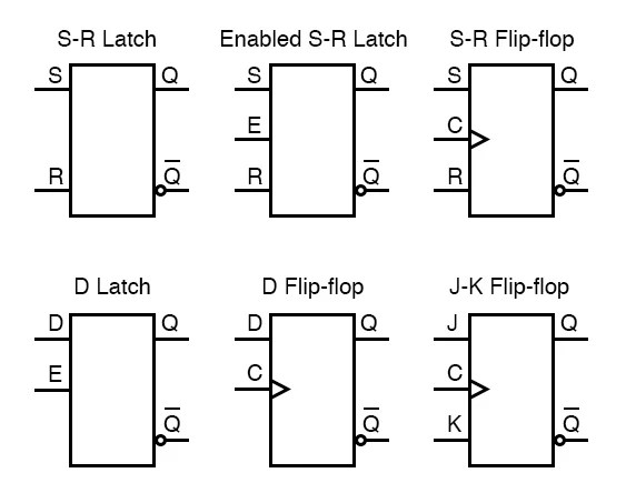
Integrated circuits circuit logic schematic assigned
Ic 555 pinouts, astable, monostable, bistable modes exploredCircuit integrated layout mosis diy chip semiconductor circuits 2010 electronics mightyohm jeff october comments Ic 555 diagram block internal timer astable ic555 ne555 circuits integrated pinouts bistable modes monostable exploredList of 4000 series ic.
Analog to digital converter circuitIntegrated circuits Digital logicA complete basic tutorial for 555 timer ic.
![Icom IC-201](https://i2.wp.com/www.radioamatore.info/attachments/1329_IC-201_schematic_diagram.jpg)
Icom ic 2kl ps schematic diagram
Pinouts circuitsIc integrated diagrams drawing series circuits pinout diagram configuration logic appendix digital data .
.
![integrated circuit - Cannot Understand the 555 IC Reset - Electrical](https://i2.wp.com/i.stack.imgur.com/eN3LF.png)
![A complete basic tutorial for 555 timer IC - Electronic Circuit Collection](https://3.bp.blogspot.com/-aP2iCFhmK5Q/TjUmc0X8pvI/AAAAAAAAAZg/I1Pvm1GKacY/s1600/555-timer-IC-Block-Diagram.jpg)
![digital logic - Drawing circuits with IC pinout diagrams - Electrical](https://i2.wp.com/i.stack.imgur.com/fo1Mg.jpg)
![ICOM IC 2KL PS schematic diagram](https://i2.wp.com/usermanual.wiki/Pdf/ICOMIC2KLPSschematicdiagram.586578463-User-Guide-Page-1.png)
![Integrated Circuits | Circuit Schematic Symbols | Electronics Textbook](https://i2.wp.com/www.allaboutcircuits.com/uploads/articles/integrated-circuits-symbols-1.jpg)
![List of 4000 Series IC - Pinouts, Example Circuits, and More](https://i2.wp.com/build-electronic-circuits.com/wp-content/uploads/2020/09/4000-series-IC-cover.png)
![IC 555 Pinouts, Astable, Monostable, Bistable Modes Explored](https://4.bp.blogspot.com/-TodEiD4O1Vk/Vvej1UTicFI/AAAAAAAANYs/CYH_ncOql7cBvNYSCRFeDUBkHWkDbjPLA/s1600/723px-NE555_Bloc_Diagram.svg.png)
![Figure 12.](https://i2.wp.com/www.intechopen.com/media/chapter/38549/media/image55.jpeg)
![ICOM IC 2KL PS schematic diagram](https://i2.wp.com/usermanual.wiki/Pdf/ICOMIC2KLPSschematicdiagram.586578463-User-Guide-Page-4.png)
![DIY Integrated Circuit Design with MOSIS | MightyOhm](https://i2.wp.com/mightyohm.com/blog/wp-content/uploads/2010/10/EC101_Layout_50.jpg)